Executive Summary
Telecommunication service providers (CoSPs) and Enterprises are following an industry transformation of moving to a cloud-based IT infrastructure to reduce cost by leveraging a shared execution environment based on Common Off The Shelf (COTS) servers. Telcos have the additional burden of moving from dedicated fixed function hardware with a vertically integrated software stack to COTS hardware where independent software applications must seamlessly integrate well, inter-operate and meet the stringent Service Level Agreements (SLAs) thereby ensuring the required Service Assurance.
The requirement for Highly Available (HA) applications and services does not change during this migration adding to the burden that the target cloud infrastructure must provide equivalent mechanisms for High Availability. For example, CoSPs will still require 5NINES (99.999%) of availability for services; a feature that Telco customers rely upon. In addition, enterprises often rely on applications where a single second of unavailability could incur millions of dollars in lost revenue. For many large service providers and enterprises the public cloud is not an option due to cost or security issues. A private cloud infrastructure provider that can deliver a level of high availability expected by these large customers stands to acquire a large and loyal following. [Sunku → Is there a proof for this that we can add in reference section? alternatively we could make it easy and say private cloud is preferred over public cloud.]
Introduction
This paper ...
Key Requirements
- Provide traditional levels of availability in a cloud environment, (5NINES)
- Provide a monitoring and event detection framework that distributes fault information to various listeners with very low latency (<10's of milliseconds)
- Provide a local remediation controller that can react quickly (<10's of milliseconds) to host faults, communicate the filtered fault information to local VMs or containers for quick reaction by the application / service.
- For a cloud infrastructure, the network assumes a larger role in availability than individual compute hosts. Provide fast detection and localization (host vs switch) of network failures through interface monitoring, path fault detection, and interaction with an the underlying software defined network control (For example, ODL)
- Provide availability mechanisms for both current virtualization environments and future containerization environments orchestrated by container management applications like Kubernetes, etc.
- Leverage the fast fault relay platform to provide a common transport mechanism for faults, events, telemetry, and logging.
- A high-availability framework cannot have humans in the remediation and recovery process if 5NINES of availability is a goal. Logging information is provided for detailed, postmortem analysis of infrastructure problems.
CoSP Requirements And Definitions
The following sections briefly introduce definitions and terminology that will be used in the remainder of the document.
Key terminology for Service Availability in NFV / networking services context
Network Element (NE) - a physical (PNF) or virtualized (VNF) element deployed in the network.
Virtual Function (VF) - a function that is not responsible for network transport / datapath services. This term is used to differentiate between the two categories of functions deployed in the NFV system - i.e. functions that are used to provide underlying network services (e.g. information transport services) and services that depend on the network. VFs are typically like any other application deployed in the cloud in terms of their characteristics.
Virtual Network Function (VNF) - a virtualized Network Element or component of virtualized network element service that is used, typically in association with other VNFs and/or PNFs to provide a specific network service or set of network services.
Physical Network Function (PNF) - a term used in the context of NFV system to refer to the physical network elements.
Network Element Outage - an event where network element fails to provide a service as a result of a failure for the period longer than the minimum outage threshold. A network element outage will not necessarily directly cause a service outage if redundant network element(s) are available to perform the associated function(s), and hence necessity of high availability.
Network Element Availability - the probability that a network element (either PNF or VNF) can provide service at any instant. NE availability is an average availability for the total population of the NEs of the same type. Note that the statistical nature of this metric implies that some instances of the network element in the total population of NEs may experience zero downtime per year, while some others may experience much greater downtime. NE availability, unless otherwise stated is typically expressed as percentage of total time (e.g. 99.999%) that its associated service(s) is/are available.
Network Element Un-Availability - the probability that a network element (PNF or VNF) can not provide service at any instant, i.e. U=1-NE Availability; for engineering purposes, the Downtime Performance Measurement (DPM) is generally used instead of the time-fractional form of target as it is a form that can be used for setting engineering level targets and tested.
Network Element Reliability - the probability that a network element (PNF or VNF) will continue to operate for a specified period of time. Reliability can also be expressed in terms of Mean Time Between Failures (MTBF) or outage frequency (e.g. Outage Frequency Measurement (OFM), outages per year).
Failure - an event where an entity (e.g. system, equipment, subsystem or component) fails to perform its intended function. A failure does not necessarily always directly result on Service Outage, depending on the redundancy, usage state etc. aspects at the time of the failure event.
Failure Mode - a mechanism or category of causes that may cause a failure to occur. Examples include Hardware (HW) failures, Software (SW) failures, procedural errors, unmanaged overload conditions, security related incidents or environmental causes (power outages, cooling failures, fires, floods, storms, earthquakes, tsunamis, etc.).
Service Availability (A) - the probability that an entity can provide its associated, specific service (or services) at any instant. Service is available when the system is able to fulfill the arriving new service requests (this property is also referred as Service Accessibility). Typically expressed as A=uptime / (uptime+downtime), also often written as A=MTBF/(MTBF+MTTR) with "R" in MTTR having slightly different meanings depending on redundancy configuration. In ETSI NFV REL documents (REL-001), this aspect of availability is referred as "Service Accessibility".
Service Un-Availability (UA) - from Service Availability, U=1-A; for engineering purposes, the DPM is generally used instead of the time-fractional form of target as it is a form that can be used for setting engineering level targets and tested.
High Availability (HA) - A property of the system, application or service of having very high ratio of uptime compared to total time. In the context of "carrier grade" telecommunications systems, unless explicitly specified, High Availability systems are generally expected to provide Service Availability levels of five to six nines for services associated with a specific network element.
Service Reliability - the ability of a system to provide service (i.e. perform its required functions) under stated conditions for a specified period of time.
Service Continuity - the ability of a system to maintain the current services without disruption. As an example, ability to continue established call without interruption, or ability to continue established TCP session through session-stateful firewall. Service continuity for stateful services (which are typical in networking) requires protection of the associated state with mechanisms such as checkpointing. State protection is primarily responsibility of the VNF implementer.
Service Outage (SO)- an event where service provider fails to provide a service as a result of a failure for the period longer than the minimum outage threshold.
Service Outage Attribution - a set of mechanisms and processes to determine the responsible party that is a cause of an outage. Associated processes and mechanisms typically include root cause analysis.
Reportable Service Outage - an outage of the specific service, which exceeds the outage threshold associated with a specific SO reporting authority. Reportable Service Outages for network services are associated with voluntary SO reporting organizations (e.g. Quest Forum outage reporting) or regulatory reporting requirements (e.g. US FCC reporting requirements, European Community reporting requirements, and other national / regional authorities reporting requirements). While specific requirements with respect to the reportable outages vary by authority and by specific service, the associated reporting requirements are usually expressed through some combination of the service impact (e.g. thousands of users affected) and outage duration. For the purposes of this document, we use 15 seconds as the RSO time-threshold target (based on TL9000 reporting threshold). The implied objective is that for all outages, we want to always set the remediation time objectives to stay well under the 15 second threshold.
Service Level Agreement (SLA) - an explicit (mutually agreed on) or implicit (stated by operator in terms of specific service) agreement between service providing party (typically network operator) and service user party that specifies the key performance indicators, associated metrics and performance objectives, penalties, etc. aspects that define the expectations for the service level as well as consequences of non-compliance. As the SLA is essentially contractual relationship, and can include parameters that are not necessarily visible / relevant to the network element / service level (e.g. pricing, penalties, incident response times etc.), only a subset of the SLA objectives are generally directly applicable to network service assurance.
Service Level Objective (SLO) - a specific service level key performance indicator (metric) and its associated numerical target value as defined in SLA.
Service Assurance - a set of mechanisms and processes in place to monitor and enforce service compliance to the SLOs which are specified in associated SLA.
Downtime Performance Measurement (DPM) - Total Downtime DPM, Partial Downtime DPM
Outage Frequency Measurement - Total Outage Frequency, Partial Outage Frequency; MTBF (hours) = (1/OFM)*8760
Failure Rate (lambda) - 1/MTBF
Failures in Time (FIT) - generally used in HW context, this is number of expected failures per one billion hours of operation of component or system.
Mean Time Between Failures (MTBF) - mean time between failures; unless otherwise specified, typically expressed in hours. For HW elements, this is based on "steady-state" failure rate, specifically excluding early failures ("infant mortality") and wear-out failures.
Mean Time to Remediate (MTTRem in this document) - Mean time to remediate the service, (i.e. restore Service Availability / Service Continuity) after occurrence of Fault, Failure or Error leading to Service Outage or Unavailability.
Mean Time to Recover (MTTRec in this document) - Mean time to recover the system to intended configuration, including redundancy configuration and state of the redundant resources after fault, failure or outage.
Mean Time to Repair (MTTRep in this document) - Mean time to repair a failed component. Used when manual (human) intervention is required to remove and replace the failed component, typically in the context of the physical HW failures.
Single Fault/Failure Tolerance - a High Availability system design and validation target where the single fault tolerance is considered to be the requirement, and multiple faults are either not considered at all or handled at "best effort" basis. For the physical network elements that has system scope that is constrained by the physical design, single failure tolerance is commonly considered to be adequate. Initially, we will focus on single failure tolerance only.
Multiple Fault/Failure Tolerance - a High Availability system design and validation target where the specified multiple simultaneous fault tolerance is considered to be the requirement. To constrain the test and validation efforts, multi-fault tolerance is usually limited to specific set of conditions. In addition or instead to systemic design, semi-randomized time/scope related testing processes with variety degrees of multiple simultaneous faults are often used. Large cloud configurations are likely experience multiple faults simultaneously, but this does not necessarily imply that from single applications perspective the probability of encountering such faults simultaneously in redundant components is higher than physical "box" design. Multiple fault tolerant application designs typically maximize the use of parallelism and utilize N+1 and N:1 redundancy schemes, which allow reduction of redundancy, increase of reliability and conversion of some of the failures to capacity events rather than availability events (but for stateful services, while affected service user population is smaller, these will still lead cause service unavailability for the affected fraction of the users). One reason for the goal of moving towards "microservices" type architectures is the increased resiliency against multiple failures as compared to typical active-standby structures that have traditionally been used extensively as a basis of redundancy in telco SW systems.
Service Availability and Continuity Targets and their Impacts on Infrastructure services
Telecommunications services are generally classified as part of the "critical infrastructure" by the regulatory bodies, and have various performance objectives that are set by the regulators and/or standardization bodies, including requirements for outage reporting and penalties associated for non-compliances, which are service and/or region specific. Implicitly, the infrastructure (in the context of this document this includes NFVI and VIM services) that is used to provide these services becomes part of the critical infrastructure and is subject to certain requirements in terms of availability, continuity, security, disaster recovery etc. In addition to regulatory constraints, the service outages cause direct (in terms of penalties and lost revenues) and indirect (in terms of customer churn, reputation etc.) monetary losses for the operators. While the service criticality, outage impact and other parameters vary by service, the most critical services (e.g. regulated services and safety-relevant services such as 911 call handling) determine the availability and reliability related design targets for the underlying infrastructure.
As compared to the physical and/or software based network element designs of the past telecommunication networks, move to SDN/NFV controlled infrastructure and general trend of "network softwarization" changes both the business relationships between the suppliers and operators, as well as the implementation responsibilities of the associated R&A related mechanisms. Generally, in the past network elements were vertically integrated systems where NE supplier was responsible for all aspects of the system design, integration and testing, including reliability and availability related mechanisms. While such systems commonly utilized commercial hardware and software components (including open source SW such as Linux), the responsibility for the availability related metrics from the operator's perspective was always associated with the system supplier. In cases where the system incorporated 3rd party hardware and/or software, then any "flow-down" requirements and potential responsibilities for associated performance penalties for the sub-suppliers were established by mutual agreement(s) of the system supplier (NE vendor) and its technology suppliers. To the some extent this model continues with the large network equipment vendors (NEPs) in the context of the NFV system, i.e. NEP takes the OpenStack and Linux distribution and "hardens" it to meet their "carrier grade" performance objectives and sells the resulting system to the operators. However, this model is against the objectives of the NFV targets set by the operators, which include the breaking of the vertically integrated vendor specific "silos" to e.g. separate hardware, infrastructure software and application SW (VNFs) vendor specific parts. In the early adoption phase where the NFV system is presently, the lack of standards or mutually agreed open source solutions leads to the NEPs and/or leading operators to fill the associated gaps as they see fit. While the resulting systems may be able to meet the functional and non-functional requirements, including the service availability and continuity related performance metrics and targets they fail on the interoperability aspects - no two implementations are same, and associated interfaces and APIs are also different, which makes each combination of system components (HW, NFVI, VIM, VNFM, NFVO, OSS/BSS etc.) integration exercise that someone needs to undertake. While at least some of the large NEP customers are working to enhance the VIM/NFVI level components, only some of them are open sourcing the associated work to differing degrees, while others are keeping the enhancements for themselves. The result is continuing fragmentation of the NFV system, which in the worst case is directly visible for the VNF - system interfaces as needed to support interoperability in both execution environment interfaces (VNF to VIM) as well as to interfaces between VNF to MANO system.
The key objective of the SA work is to work with the NEPs, network operators, open source communities and projects to establish an open source based solution to address the availability and reliability related aspects of the decomposed system (currently focused on NFVI and VIM parts of the ETSI reference architecture).
Traditionally, in the context of the specific network element design, the services and associated service availability and service continuity objectives were specified at the high level, and associated downtime targets allocated to the hardware and software subsystems in the context of the specific implementation architecture constrained system configurations. The allocations of the performance objectives were typically determined based on the prescriptive modeling in early stages of the design (using R&A models of the configuration based on common modeling practices such as reliability block diagrams and/or markov reward models), followed by the testing and/or field data performance driven validation of the models in later stages (process called "descriptive modeling", which used the same model but driven by the actual measured performance parameters). The same processes were also used to allocate the availability related performance objectives (such as un-availability, remediation times, fault coverage, etc. parameters) between the parties involved on the realization of the system. Same high level processes can be used to establish a basis understanding of the relationships between the services provided by the applications and the services provided by the infrastructure that they application services depend on, as well as the associated service availability and continuity related objectives. However, due to diversity of the application designs, services and service specific targets, as well as variation on the infrastructure implementation options, we are necessarily limited to general relationships and high level objectives only rather than full, application instance specific design and analysis. This exercise is still considered to be useful for establishing the generic understanding on the availability related targets flowing down from the high level (application / VNF level) performance objectives. For simplicity, the following overview uses RBDs for basis of establishment of the high level relationships of the availability of the VNFs in the context of NFV system. The intent here is not to be a tutorial on availability modeling, see e.g. NFV ISG REL-003 document for the background material in the NFV context. It should also be noted that RBDs are not sufficient to fully model complex time-based behaviours (such as failure rates, recovery times and fault coverage), but unlike MRMs, they are easy to construct, understand and compute and sufficient for establishment of basis for high level allocations based on structural relationships and dependencies between software and hardware elements.
A common numerical availability target associated with the so called "carrier grade" systems that we are required to be able to meet in NFV systems as well is 5NINES Availability or higher (there are elements that require higher availability level targets), but this is generally considered to be the low threshold for the "carrier grade" availability. As availability target is meaningless without specifying availability of "what" along the target, this generally is taken to mean 99.999% availability of a specific network element and its associated service(s), i.e. network element availability across the population of network elements of same type, translating to DPM target of ~315 sec/NE/year. The target is sufficiently high that, at least when combined with service continuity requirement it is expected to imply the need for some level of redundancy (at least two components in e.g. active-standby redundancy configuration). Since our hypothetical virtualized network element relies on at least the NFVI+VIM, as well as GVNFM+NFVO services for its operation, we can draw a following high level series RBD that establishes these dependencies:
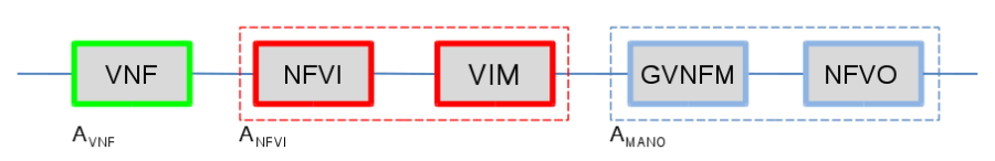
From the above, we can see that for the service to be available, both blocks need to be available. We can also see that to meet the service availability target of 5NINES, each of the components in series need to be more available than 5NINES (as it is unreasonable to expect the NFVI+VIM+GVNFM combination to be 100% available, even with redundancy). Note that the availability of the series RBD can be obtained by multiplying the availabilities of individual components, or alternatively by adding the associated component DPMs. So, if we would have each of blocks 5NINES available, the combined availability would be .99999^3=.99997, which translates to unavailability of 1-A * 31536000 sec/y = 946 sec/y, i.e. one third of the target. The high level process of target setting is referred to availability allocation, and is generally done based on allocation of downtime in terms of time rather than using NINES (although both are equivalent, downtime is much easier to use as an performance objective).
To further expand the above example, we can incorporate a bit more detail by drawing a more detailed RBD as follows to account to parallel-series relationships of the VNF components and services that are within each top level block:
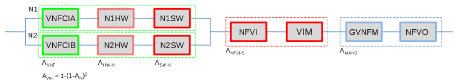
If the combined availability of the VNF SW components, its embedded OS instance and all of the supporting node HW and SW components of the single node is three nines (0.999), the availability associated with the dual-redundant VNF instantiated in anti-affinity configuration in two independent, homogeneous compute nodes N1 and N2 will be 1-(1-.999)^2 = 0.999999, i.e. six nines for the pair. Since the pair depends on the VIM and other MANO functionality for the remediation operation (i.e. failover), it depends on those components that are in series, and their availability needs to be considered to determine the VNF availability. When we combine the VNF in node pair availability with the series elements (NFVI+VIM shared components and rest of the MANO system), we get total availability for the chain of: .999999 (VNF) x .999999 x .999999 = .999997, which is well over 5NINES (based on assumed 6NINES availability of the critical path functionality in the VIM and MANO elements). Note that as this is the simple RBD calculation, the other aspects such as fault detection coverage, failover failure probability, or failover time are not modeled (implied assumption is 100% coverage for service affecting faults, zero failover time and perfect failover - which are all unrealistic in real implementation), and the time spent on the associated processes add directly to the downtime (Service Un-Availability). Therefore, this is a maximum possible availability that can be achieved. This is key reason for why the critical path from the fault management cycle (from the fault detection to the end of remediation phase) needs to be completed as quickly as feasible - even with the redundancy in place, until the remediation processes have been completed, the service is down from the user's perspective.
From our very simple (i.e. simplest possible) high-availability workload configuration with only two VNF Component Instances, we could already see that to achieve the 5NINES performance by the application, we will need to have better than 5NINES performance for the critical infrastructure services that the application depends on (such as network, storage when used, and API services that are used by the application VNF e.g. to perform remediation and recovery actions). In reality, the VNFs have internal structure, are composed of multiple VNFCIs with potentially differing redundancy configurations, and their corresponding RBDs look significantly more complex than previous example. It is not uncommon that single complex VNF would have 5-10 stages of components in series on the associated RBD, and the move towards microservices architectures that operators are pushing vendors towards will increases this even more. Furthermore, the services are composed of chains of the NEs (physical and/or virtual), which increases the number of elements that the service depends on. All this means that for the equivalent Service Availability, the availability of the chained elements (and the elements of the infrastructure they depend on) must be proportionally higher. In addition, from the OpenStack cloud shared services perspective, a realization of many network services requires use of components located in multiple clouds even in the single operator scenario - typical configuration to support end to end service would have at least three separate clouds in series: access/edge cloud 1, core cloud, and access/edge cloud 2, which implies that we will have three independent openstack service regions in series within the overall chain. The following picture, taken from ETSI NFV REL-003 is an illustrative example of availability effect from E2E service availability perspective, where the blue blocks represent the availability of service chains within the specific cloud instances. 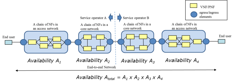
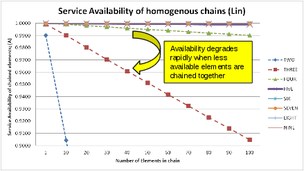
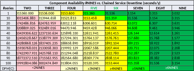
To illustrate the cumulative effect of the homogeneous chained elements to the Service Availability, the following table provides an overview of the expected availability expressed in number of NINES (based on RBD only calculation, which have the limitations outline before, i.e. the associated performance statement is optimistic). As a target setting, NFV system should be able to support applications (VNFs, VFs) / services at least in yellow and light green zones.
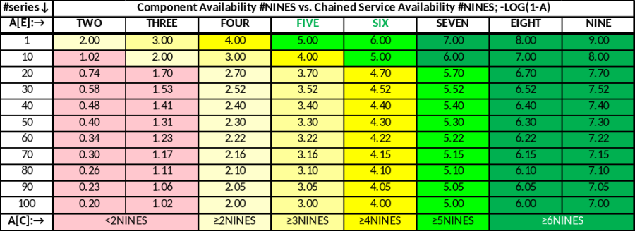
Same table as a (linear) graph illustrates the effect of individual chain element availability (also, keep in mind that the chain availability cannot be higher than the availability performance of the lowest performing element in the chain:
Finally, equivalent in the DPMs (Seconds/NE/Y or Seconds/Service/Y, depending on the scope of the top level availability specification):
The top level allocations of the DPM based on 10% of total NE and/or service downtime (typical from similar systems from the past efforts, and also stated performance by competition) looks like follows:
High Level Availability Allocation Calculation; all causes | |||||||||||||
|---|---|---|---|---|---|---|---|---|---|---|---|---|---|
Atarget | DPM-Tot (s/y) | %HW | %ISW (≤VIM) | %ISW (>VIM) | %APP (SW) | %OPER | %TOT | HW DPM | ISW (≤VIM) DPM | ISW (>VIM) DPM | APPSW DPM | OPER DPM |
|
0.99999 | 315.3599999986 | 10 | 10 | 10 | 50 | 20 | 100 | 31.54 | 31.54 | 31.54 | 157.68 | 63.07 | DPM (sec/NE/y) |
|
|
|
|
|
|
|
| 0.999999 | 0.999999 | 0.999999 | 0.999995 | 0.999998 | A |
5 |
|
|
|
|
|
|
| 6.00 | 6.00 | 6.00 | 5.30 | 5.70 | #NINES |
0.999999 | 31.54 | 10 | 10 | 10 | 50 | 20 | 100 | 3.15 | 3.15 | 3.15 | 15.77 | 6.31 | DPM (sec/NE/y) |
|
|
|
|
|
|
|
| 0.9999999 | 0.9999999 | 0.9999999 | 0.9999995 | 0.9999998 | A |
6 |
|
|
|
|
|
|
| 7.00 | 7.00 | 7.00 | 6.30 | 6.70 | #NINES |
As a sanity check for the above targets, we calculated the top level un-availability attributions based on the reported service outage data from European Community summary report from 2015, as follows:
Weighted allocation check (enisa 2015 dataset) |
|
|
|
|
|
|---|---|---|---|---|---|
Category | %tot (all incidents) | Iavg (ksub) | MTTR (hrs) | RPN | RPN% |
System Failure | 68.8 | 1600 | 25 | 27520 | 80.61 |
Human Error | 21.7 | 1400 | 9 | 2734 | 8.01 |
Malicious Act | 8 | 1000 | 47 | 3760 | 11.01 |
Natural Phenom | 1.5 | 200 | 42 | 126 | 0.37 |
Total | 100 |
|
| 34140 | 100 |
Approximately 70% of all causes are attributable to the "system failures", which includes all Network elements and their HW and SW attributable failures. When weighted for impact (average of thousands of subscribers affected by outage x impact duration), this translates to approximately 80% of total weighted downtime, with remaining 20% of the weighted downtime associated with operator attributable / external causes. This aligns with our top level allocation (10+10+10+50%=80% for network elements, and remaining 20% for the external, operator attributable causes). This is also well aligned with past availability / downtime performance data from real operator networks, as well as high level downtime budget allocations used for the engineering purposes.
Failover time of carrier-grade network services is often characterized by the 50ms target. To further determine if and when this applies to us, it is necessary to understand the basics of its origin as well as applicability in the context of the cloud services. The origins of the 50ms target trace back to the redundancy mechanisms in early TDM transport systems, and has firmly established itself as a target for the associated replacement techniques over time. It is commonly used target in the specifications of the ring topologies, optical transport networks, and the subsequent mechanisms associated with replacement of such topologies with mesh topologies, e.g. in context of IP/MPLS based transport services. It should be noted that this applies to distributed networks, and therefore is especially hard to meet in the context of the large topologies, where speed-of light propagation in fiber related issues become relevant in the context of propagating the fault indications between the associated elements. Generally speaking, the common prerequisites for realization of this tough target include: very fast fault detection times (order of single 10's of milliseconds or less), availability of pre-computed back-up paths for each specific failure mode (e.g. link / path failure), availability of resources pre-allocated and pre-configured to handle the failed over traffic load after the fault is detected. To overcome "limitations" of speed-of-light related issues, the network can be concatenated to smaller recovery regions that can individually satisfy the requirement, and assuming that each region, irrespective of its implementation can meet the target performance, the Network Service can also meet them at least on the context of the independent, single failures. At a first observation, it might appear that this is not relevant to the NFVI clouds - after all, we will not be taking over e.g. the Sonet rings, as they are physical systems that cannot be simply eliminated and moved to "cloud". However, routers and other packet processing entities are targets for moving to cloud based implementations, and even elements that are not considered to be directly on "transport service" path may need to interact or even directly integrate with transport services, and in the context of the service that requires fast restoration requirements, whatever is on the end-to-end path may be subjected to such requirements. In the traditional, physical system "box" design, the associated key element which is on the path of the service realization is the switching subsystem of the box. To negate the effects associated with long failover times of the physical switch elements to the overall service switchover performance, it is necessary that those switching components exhibit failover time properties that are at least as good as the network level mechanism, but are usually engineered to much higher standards, which is relatively simple to do within constrained topology of the individual box (sub-10 ms designs for fabric failover time are not uncommon in physical network elements). When we decompose such functions and move them to the cloud, the NFVI fabric (underlay and overlay, depending on how the applications consume these resources) replaces the fabric that used to be embedded within the box. Therefore, to achieve similar performance, the elements of the fabric when subjected to equivalent performance constraints as well as the associated pre-requisites (such as allocation of precomputed backup paths mentioned above) should be able to meet the similar order of failover time requirements as the fabric implementation on the physical systems. Otherwise, while we might be surrounded by the access network that meets the 50ms targets at the network level, and metro/core transport network that meets the 50ms requirements, and our fabric and elements in the path would have say 1 second failover time, it would be impossible to provide a network service that consistently meets the 50ms target, as every time the NFVI network instance on the path would fail, network service user would experience the Service Outage of 1 sec (as like with the Service Availability, the lowest performing "weakest link" element in the chain determines the achievable performance).
Some examples of the associated fail-over time requirements that require this level of performance include e.g. the following (many more are available, in case of needed we can provide a longer list of references discussing how this is to be accomplished in NFV/SDN controlled NFVI network implementations):
1.) ETSI REL-001 statements that goal is to achieve Service Level that are equivalent or better than service levels in the physical systems, and especially the REL-001 problem statement in section 4.1.: "Whereas in the IT domain outages lasting seconds are tolerable and the service user typically initiates retries, in the telecom domain there is an underlying service expectation that outages will be below recognizable level (i.e. milliseconds), and service remediation (recovery) is performed automatically."
2.) ETSI IFA requirements to support anti-affinity policies in context of allocation of virtualized network resources (which is prerequisite for being able to support redundancy mechanisms based on path diversity - i.e. anti-affinitized backup paths)
3.) Examples of SLAs of end customer services, which require same order of magnitude failover performance (60-100ms, depending on service); note that as SLAs are essentially components of bilateral contracts, they are seldom made public. Here is one example of public document from US Government's common SLA requirements, which includes Service Availability and various KPIs, including failover times for select services: GSA Networx SLAs
4.) Failover time requirements in 5G crosshaul project - 4 out of 5 use cases states "time of recovery after failure" of 50 ms or less, while remaining one has 100ms target: 5G CrossHaul.
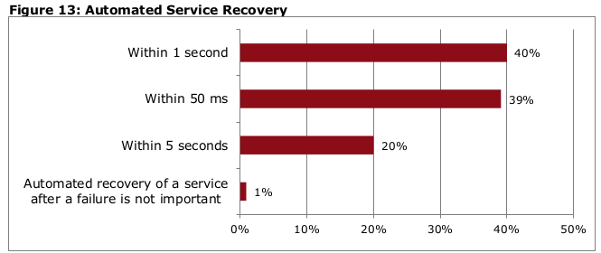
5.) An aggregated responses of Red Hat commissioned Heavy Reading NFV operator survey of 128 service providers, "Telco Requirements for NFVI", November 2016, which had a specific question on the failover time. Associated graph on response distribution is replicated below for convenience; 40% of respondents were asking for 50ms. In addition, the associated clarification text on the responses stated "Those already executing their NFV strategies were much more likely than those who are not to say that recovery time should be within 50 ms"
To summarize, the high level engineering targets derived from the application level requirements that we use as service independent availability metrics for the NFVI infrastructure, as well as to establish target values for parameters to be measured on testing are:
- Maximum Un-Availability (DPM) of 31.5 seconds per year for all attributable causes (i.e. all SW, and all implied operational processes such as updates/upgrades)
- Maximum failover time for the critical services of 50 ms or less for specific cases, i.e. not universally (primarily applicable to the critical NFVI fabric / overlay network services, their remediation when responsibility of the infrastructure, and supporting processes such as correlation and propagation of the fault event related notification messages)
- 100% success rate on accuracy of the localization process to the correct smallest fault containment region that contains the associated root cause, and is subject to subsequent remediation actions
- 100% success rate for the fault containment processes, as required to prevent fault propagation across the containment region boundaries
- 100% fault detection coverage for all critical services
- 100% failover / switchover success rate
In practice, this translates to the need to target as close as feasible to zero guest impact for all critical services, and to the need to minimize the downtime associated with both the guest (VNF, VF) initiated processes (such as failover), NFVI/VIM initiated processes, such as failovers, operational and optimization related processes (such as live migration or updates/upgrades). All operations, irrespective of the part of the system that is responsible for remediation actions needs to be fully automated, i.e. subject to "auto-remediation" processes (if there are humans in the loop, the timeline targets are impossible to meet, and we are implicitly already experiencing an outage at that point). 100% targets for the coverage, accuracy and operation success metrics are not likely to be realizable in practice, and will lead to un-availability and outages when they fail. However, this underscores the importance of the reliability of these processes, and suggest need for comprehensive testing (which itself requires large enough sampling of varying fault injections to account to both asynchronous nature of the injection processes as well as statistical nature of the associated parameters), along with the zero-tolerance policy to be adopted on fixing the identified issues. To avoid overdesign, and focus our resources to improvements in critical areas first, we will discuss the targets on per service basis after further classification of the top level metrics based on the risk (combination of expected impact and activation probability) in subsequent chapters of this document.
Also, we will further document the expectation of the responsibilities between the guests and the infrastructure that form the basis of the successful implementation of High Availability services (currently, it is expected that most of the functions associated with application availability such as failovers of redundant entities as well as state protection required to support the service continuity are fully application's responsibility, and infrastructure is limited to implementation of detection, notification and infrastructure Service Availability related processes only, including the services that are expected to be invoked by the application as part of their recovery processes). When infrastructure contains 3rd party elements, such as physical network elements that are implemented as High-Availability network elements, the associated availability performance is fully attributable to such elements. The same applies to all infrastructure components that support internal redundancy mechanisms, e.g. power and cooling redundancy related mechanisms when implemented within physical element such as an individual server node to improve its availability performance against expected common failure modes.
This document is presently focused on the Service Availability in context of the first order effects (i.e. dealing with failures of the system components). It should be noted that other aspects of the Service Assurance are tightly coupled to availability performance and need to be addressed as well (e.g. service degradation to the level that is "unacceptable" is commonly counted as availability event, even its management is associated with the Performance Management instead of Fault Management, or failure of service as a result of successful security related malicious attack incident against infrastructure can also be counted towards the system unavailability as infrastructure attributable cause). However, such aspects are currently out of scope of this EPIC, and may be added to subsequent versions of this or other EPICs later.
Fault Management Cycle
The following diagram depicts a generalized phasing of the Fault Management Cycle, which applies during the operational state of resources or subsystems that are subject to the availability constraints and associated mechanisms (primarily based on redundancy schemes in the context of the High Availability systems).
During the normal state, when the system is operational and in various states of service (whether active or standby resource), monitored entities are subject to the fault detection mechanisms. This phase is referred to detection in the FM cycle. Independently of the fault detection mechanisms, system may also utilize predictive mechanisms with the goal to identify the impending failures before they occur (this is particularly useful in the context of resource depletion etc. failure modes that are expected to get activated with high degree of confidence). After fault is detected, it needs to be localized to quickly identify the probable cause with sufficient level of confidence required to determine the associated actions to be taken in subsequent phases. Isolation (Fencing) phase is used to ensure that the failed entity is decoupled from the rest of the system, and is particularly important when multiple redundant, stateful entities are subject to risk of shared state corruption (e.g. to avoid problems associated with so called "split-brain" situations). Remediation phase is responsible of restoring the associated service, typically switching to the associated redundant resources. After the remediation related processes are completed, the recovery phase is responsible on restoring the intended configuration, including full redundancy, and re-establishing the appropriate state of the redundant resources as required to support service continuity. For the pooled, homogenous resources in the cloud, the repair processes can be deferred and batched to substantially higher MTTR intervals than in traditional non-pooled systems (subject to the availability of the sufficient resources to support workload and failed resources), which reduces urgency of repair operations, which is important operational cost driver especially in typical distributed / unmanned site configurations. For the NFVI resources that cannot be pooled for deferred repairs due to excessive risk associated with the outages due to second failure, such as e.g. switches in small configurations, the conventional physical infrastructure repair times (typically 4hr window including dispatch, travel and repair times) are still required.
The detection to end of remediation phases of the FM cycle are time critical, as the service is subject to outage or degradation during this period. For the most demanding applications in Telco space, the target timeline for all processes is traditionally 50ms, which determines the design target "budget" for the associated common critical path processes such as messaging, event correlation etc. It is not expected that all failure modes are subject to the same targets, and generally targets are relaxed when moving up on the dependency hierarchy, with target of the lower layer remediation processes to be allowed to function before higher layers attempt to take actions on the same underlying fault. 50ms targets are typically associated with shared common network resources which result in broad-impact (in terms of affected dependent entities) and immediate outages upon activation, but due to the nature of the NFV, VNFs being potentially part of the network datapath, such targets may in some cases be applicable to VNFCIs themselves. It is also expected that the supporting infrastructure is in place for the tightest remediation time targets, including redundant resources that are at same state as the active resources, pre-computed backup paths to facilitate distributed and parallelized remediation processes, etc. Overall, the timeline is usually considered to be more important than absolute correctness on e.g. localization processes - especially in the cases with partial failures it is often better to utilize fail-fast policy and convert them to fail-stop failures than expend lots of time to attempt to figure what can be done to get back to the pre-event condition locally - in any case, all entities subject to high availability targets need to be able to recover from any single failure, and that is what the on-line redundancy resources are for.
Recovery, diagnosis and repair times are less time critical, but still relevant to availability performance due to subject of the outages through second failure exposure during the recovery period. For the pooled resources, this situation is generally substantially better than in physical systems, as the timelines are typically in single minutes vs. 4 hr MTTR window outlined above for the physical systems. After completion of the physical repair (when applicable), the repaired resource is placed to pool (if pooled resource such as general purpose NFVI compute node), or placed back in service if dedicated resource (switch or other such specific purpose resource). For above reasons, these are not subject to optimization efforts, and we initially focus just on measuring the associated times. Irrespective of whether the resources are pooled or not, the failed resources need to be positively identified to the Field-Replaceable Unit (FRU) level to facilitate the physical repair operations. Off-line diagnosis methods are used to determine this with high level of confidence, as well as to drive re-pooling decisions for transient fault mode related failures.
Event notifications are expected on associated detection events (which drive the cycle), as well as major events associated with the subsequent state transitions. All of the FM events are subject to logging in the associated persistent event logs for future consumption of downstream processes such as availability performance monitoring, analytics, post-event reporting, and cause attribution / RCA.
The fault management cycle is related to the current epic by:
- Detection – A low-latency, low-overhead mechanism for the cloud (Fast Fault Framework)
- Localization – A combination of physical to virtual mapping and fault trees inside CloudForms
- Isolation (Fencing) – TDB but eventually a combination of Application, Kubernetes and ODL for network isolation
- Remediation – TDB. Once the detection, location, and delivery elements have been addressed, remediation is a combination of application and cloud.
- Recovery – TDB Recovery involves the MANO / NFVO layer as new instances may need to be allocated and new network paths created.
Initial focus is in detection, notification and localization related mechanisms, as those are the basic enablers that need to be in place before we can close the loop. The remediation and recovery mechanisms also have implementation requirements at multiple levels, including components that are not covered here (esp. VNFM for the application availability management related mechanisms and NFVO and higher level orchestrators / controllers for E2E service related remediations). It is expected that the phases responsible for taking remediation and recovery actions are implemented based on event driven policies, with target realization at the lowest level possible of the overall SW stack (i.e. as "close" as possible to the associated detector entities in terms of the critical components on the processing path).
Fault Management Cycle Timeline
The following diagram shows the key events of the FM cycle timeline for a generic failure. Up until the tfailure, the failed component is operating normally with a stand-by component providing redundancy. In this example, the timeline after remediation phase is shown separately for both pooled and non-pooled resources. In a pooled resource scenario, a group of resources (VMs, Containers, etc) can be reallocated from the cloud resource pool to rapidly restore the intended redundancy configuration. In non-pooled scenario, a new resource needs to be physically provided before it can be made available to serve as a stand by resource, which adds the physical repair time to the aggregate timeline. The advantage of pooled resources is that the recovery time (time for restoration of redundancy) is substantially shorter, reducing the exposure to secondary failure induced outages. At tfailure, the primary component fails and tDET (detection) begins. After the failure has been detected, the failure event must be delivered to the relevant components to either perform a recovery operation or to provide an external notification. Finally, remediation begins the process of activating the standby resource and restore the operation of the service. The target time for the series of operations is given by: TDET + TNOT + TREM < 50 ms. TREM often requires the most significant time to complete therefore, TDET + TNOT must be minimized as much as possible. After remediation is complete, the service has been restored, but the failed component is not redundant and a failure of active component could result in a substantial service outage. The recovery phase addresses this issue by bring a standby component online and configured. The recovery time can start as early as the detection time if recovery operations can occur in parallel with remediation. After recovery, the component is again redundant.
Infrastructure Services Relative Criticality
Different infrastructure services can have different impacts on the reliability of the infrastructure as a whole. Service components such as network switches can have a disproportionately high impact on the reliability of the entire infrastructure due to their connective nature. Conversely, traditionally emphasized components such as compute nodes mostly affect the VMs / Containers running on them. The following table provides a high level view of the categories of the services / entities in the NFVI and VIM sublayers of the system SW stack. This high level analysis is based on the expected risk, which is determined based on entities (guest VMs as a proxy) at risk and the fault activation probability from the guest's perspective.
The intent of this table is to prioritize the improvement efforts of the services / subsystems that represents the highest (guest) service risk first, based on the expected impact. The next steps will involve mapping all specific individual services to these categories, as well as establishing target availability (or unavailability derived remediation times) for each category. Generally, it is expected that the lowest unavailability targets are at the lowest levels of the dependency stack (which also have the highest priorities).
| Component | Impact Potential (nodes) | Impact Potential (VMs) | Failure Activation (for active nodes/service failure) | Pri |
|---|---|---|---|---|---|
CRITICAL | Fabric - spine | ~#nodes/#spines | ~#VMs/#spines | Immediate for ea. Serv user | 1 |
| Fabric - leaf | ~#nodes/#leafs | ~#VMs/#leafs | Immediate for ea. Serv user | 2 |
| Network node | ~#nodes/#nnodes | <#VMs/#nnodes | Immediate for ea. Serv user | 3 |
| Storage node | ~#nodes/#snodes | <#VMs/#snodes | Immediate for ea. Serv user | 4 |
MAJOR | Control node | #nodes | #vms | Secondary activation, all hosted services impacted | 5 |
| Control node, specific service | #nodes | #vms | Secondary activation, only specific service impacted | 6 |
CRITICAL | Compute node | 1 | #vms/node | Immediate | 7 |
| Compute node critical services | 1 | #vms/node | Immediate (compute, network, storage "critical path") | 8 |
MAJOR | Compute node non-critical services | 1 | #vms/node | Secondary (for associated control/mgmt services) | 9 |
| Compute node VM specific SW | (N/A) | 1 | Immediate for associated VM (example: QEMU) | 10 |
MINOR | Supplementary Services | #nodes | #vms | No direct activation mechanism that impact quest availability state (e.g. GUI/CLI services not used by automated processes) | 11 |
| |||||
Service Availability and Upgrades
Maximizing service availability in terms of engineering objectives translates primarily to minimization of downtime (i.e. service unavailability). This implies that we need to measure the downtime impact on testing, and improve it over time. For redundant systems, the downtime should be as close to zero as possible, at least for critical services. In addition to minimization of the downtime, we want to minimize the time that it takes to restore a fully redundant configuration, which should also be measured and target for improvements. The test procedures should be the same as used for high availability testing, with the main difference being that the test for the update/upgrade impact is done based on update/upgrade process request, instead of fault injection (HA tests). While redundancy restoration time is not as critical as service downtime, it can translate to the service outages through secondary failure exposure. Redundancy restoration time is particularly relevant metric for the services that utilize persistent storage, where the process can take relatively long time as compared to services that do not have such dependencies. While the following discussion is focused on the upgrade process, the terminology and approach are the same for High Availability in general.
As the primary objective is to ensure guest availability, we can classify the services that the guests depend on, in terms of criticality. This means that if the guest availability depends on the availability of the system service, that service itself, as well as all the services that it depends on becomes availability critical service. For the OpenStack and node services, we can broadly classify the services to following criticality categories:
- Critical: service with immediate guest outage on activation (100% activation probability): all services that guests are using "all the time". Examples include all critical compute node services (compute, network, storage), all critical shared services (centralized/CEPH storage services, system network services (including gateway node services, LBaaS when used, etc.)
- Major: service with conditional guest outage on activation (less than 100% activation probability): all services that become critical when used by the guests, typically related to API calls. Such services are all services that modify the guest / system network etc. configuration, typically invoked as part of the guest lifecycle management operations such as scaling in/out, failure remediation etc. If these services are unavailable when requested, they can directly translate to (i.e. add to) guest downtime. Generally OpenStack API services and HEAT, and ALL of the services they depend on (e.g. messaging, scheduler, databases, authentication etc.) would be in this category. Note that the activation probability for the major failures increases as the system size (number of nodes/guests) increases.
- Minor: no direct impact on guest service availability state: all services that are non-critical to the availability of the running guest's and their associated (provided) services. Example: Horizon GUI services.
The downtime targets are for all causes, including failures (all causes; HW failures and SW defect related failures), updates/upgrades etc., which means that no single cause (or category of causes) can "claim" the whole un-availability "budget". Since update/upgrade operations are performed on-demand, the performance is expected to be better than failure related performance because the system can take actions to reconfigure itself to minimize the impact (e.g. through gracefully removing the entity subject to the update from service rather than performing asynchronous remediation sequence, as is the case of the failure related actions). Target update/upgrade frequency (in terms of operations expected per year) should linearly decrease the individual update downtime allocations (e.g. if you expect Devops environment with monthly updates, then ea. Update can take 1/12th of allocated yearly downtime).
Proposed yearly unavailability targets for the update/upgrade related outages per category, in HA configuration:
Category / Description | Target Time (Max. Service Un-Availability DPM) |
|---|---|
Critical guest impact services | Less than 3 seconds/year |
Major guest impact services | Less than 15 seconds/year |
Minor guest impact services | Less than 5 minutes/year |
Maximum time for operating with degraded/no redundancy configuration due to upgrades | 5 minutes/year for all nodes/services, except 30 minutes/year for nodes/services that require database / other persistent storage migrations during update process |
The following table maps OpenStack and infrastructure services to the appropriate risk level. Risk is broken into categories of runtime impact, upgrade impact. A OpenStack service's runtime functionality can varying degrees of impact on the availability of the infrastructure. For example, if the runtime services of the Ceph backend for cinder fail, user services that depend upon persistence storage may fail immediately. However, if the cinder API fails, user services might see a degradation in functionality if new volumes cannot be created, but may continue to function. As another example, if the ability of nova to create new VMs is lost, user services might be degraded in that they cannot scale up. While the loss of the VM migration would affect the infrastructure's ability to react to node failures.
The intersection of the cloud's philosophy of fail and retry and the more traditional telco model of always available need to be explored. However, OpenStack services themselves need to be resilient in that the service may fail, but should not leave any permanent errors in the infrastructures such as orphaned processes or memory leaks. For example, it may be ok for a nova boot command to fail before completion if a control plane host fails. However, that failure should not leave any VM or networks that need to be cleaned up manually. If an OpenStack service cannot be made to be tolerant of control plane failure, the services behaviour during that failure should be documented. In any event, OpenStack service failures should be designed to notify of their failure as quickly as possible. For example, if a nova boot operation fails due to a control plane host failure, the user service should be notified of the failure as quickly as possible.
Service | Runtime Impact | Upgrade Impact | API Impact |
|---|---|---|---|
Aodh | Major | Major |
|
Ceilometer | Major | Major |
|
Nova | Major | Major |
|
Ceph Monitor | Critical | Critical |
|
Cinder-Volume | Critical | Critical |
|
Cinder-Backup | Major | Minor |
|
Glance | Minor | Minor |
|
Gnocchi | Major | Major |
|
Heat | Major | Major |
|
Horizon | Minor | Minor |
|
Ironic (Overcloud) | Major | Major |
|
Ironic (Undercloud) | N/A | Critical |
|
Keystone | Major | Major |
|
Manilla | Major | Major | Is this for NFV? How widely used in general? How is it used? |
Neutron API | Critical | Critical | Failure recovery mechanisms may rely on network changes. |
Sahara | Minor | Minor |
|
Switch API | Critical | Critical |
|
Neutron-dhcp-agent | Major | Major | VMs with dhcp addresses may reboot at any time. However, critical user services should have HA mechanisms. |
Neutron-l3-agent | Critical | Critical | The L3 agent provides data path functionality for applications that require SNAT functionality. |
Neutron-metadata-agent | Major | Major | VMs may reboot during failure. However, critical user services should have HA mechanisms. |
Neutron-ovs-agent | Critical | Critical | Failure recovery mechanisms may rely on network changes. |
SDN Controller (ODL) | Critical | Critical | If in control path... |
LBaaS-API | Major | Major |
|
LBaaS-Service | Critical | Critical | Our responsibility for HAProxy version. |
Swift | Critical | Critical |
|
Manila-share | Major | Major |
|
Mongodb | Major | Major | If used..see Gnocchi |
HAProxy | Critical | Critical |
|
Galera (MariaDB) | Critical | Critical |
|
RabbitMQ | Critical | Critical |
|
Redis | Critical | Critical |
|
Virtual-IPs | Critical | Critical |
|
memcached | Critical | Critical |
|
Upgrade Process
The upgrade process in telecom has traditionally been non-service affecting. Telco system design had to take into account upgrades as a key design component. The same criteria applies for telco cloud upgrades. A "rolling-upgrade" process must be available for the cloud control plane such that components can be upgrade in stages with no impact to the services supplied by the cloud control plane. This design criteria will difficult as the cloud consists of the infrastructure operating system
For the service critical updates of compute nodes, if the node has guests running, the common expectation is that guests are migrated away before proceeding with the node update. Such migration could be based on VM migration process, but as we do not currently have support in place for live migration of the hosts that use hypervisor bypass features (SR-IOV and/or PCI passthrough), this will not be always feasible. Forced node upgrade for such scenarios would look equivalent to a failure of a node. Availability critical guests are expected to be able to recover from failures (e.g. by failing over to redundant guest), but not without any associated downtime budget, so common expectation for the updates would be to request graceful guest switchover by guest rather than just inducing the node failure as part of the upgrade process. This capability requires an interface to the guests. The VNFM should be the contact point for general VNF notifications.
For the VM migration cases, the migration performance is the critical parameter (primarily, as measured in terms of the outage period that is caused by the live migration process, and secondarily as a degradation of performance during the migration process e.g. due to memory copy overhead), and should be tested and improved over time. If migration is used as part of upgrade process, then migration should targeting already upgraded nodes to avoid the need of double migration (and associated additional downtime).
In addition to downtime metrics, the service continuity is critical - it is not acceptable to lose any of the running system configuration or other persistent state information (typically stored in the associated databases) for any of the critical or major services due to upgrade process.
During the update/upgrade campaign, it is normal that at least some of the associated upgrade targets are in different SW version states. While it may be feasible strategy in some cases (e.g. for controllers) to have two parallel versions (either in full redundancy configuration, or new service instance as additional entity) running in parallel for some services such as controllers, it is not feasible strategy for the nodes themselves. This may impose additional version compatibility in system internal interfaces (vs. API level version compatibility which is directly visible to the users). Upgrade campaign strategy needs to consider the associated version dependencies and take the dependency related ordering constraints in the account of the upgrade strategy design. Since the primary objective of this document is to distribute the update/upgrade development and/or testing to individual DFGs, they should also identify such compatibility requirements and work with upgrade DFG and/or associated dependency DFGs to design appropriate upgrade strategy.
Container Upgrades
The upgrade process for containers must meet the same requirements as outlined above. The upgrade from non-Kubernetes to Kubernetes-enabled OpenStack services is TBD.
NFV Enhanced HA Architecture
Addressing Single Point of Failure
A common goal in the design of highly available systems is the removal of single points of failure. Single points of failure can be either hardware or software components and care must be taken to ensure that each component is redundant or has some means of recovery. Emphasis is often placed on the protection of server hardware but the the network infrastructure by virtue of its connectivity plays a much larger role in the availability / reliability of a system.
The following items are needed to address SPOFs in the network:
- IPMI / DRAC connections should be redundant and connected to separate switches.
- Bonding / LAG
- OpenStack networks (Storage, Storage Management, Management, Internal API, Tenant (non-SRIOV) ) should be connected to multiple switches using the switch vendor's multi-chassis bonding mechanism (MLAG, VLT, CLAG, etc…).
- Each SR-IOV network should connect to multiple switches. For the initial version of the architecture, active/standby bonding should be used inside the VM with a bond member from each switch connection.
- A Leaf-Spine network architecture should be employed. Director should be enhanced to accommodate leaf-spine.
- Installation should include automatic discovery of networking elements and connectivity with an emphasis on verifying the required HA attributes
Fast Fault Detection and Notification Framework
A fast fault detection and distribution framework is needed to achieve telco-level reliability and availability. Telco systems are typically built with full vertical integration of hardware and software. Services running on the system have direct access to hardware events and faults. For example, carrier loss of an datapath ethernet port is typically broadcast to relevant components (local and non-local) within milliseconds enabling quick response to the failure.
The cloud infrastructure, in contrast, is hidden from applications / VNFs by design. The resulting work for this epic should define a scalable framework that allows faults to be quickly determined and fault events to be quickly delivered to both the cloud infrastructure control plane and to applications running in the cloud.
Requirements for a fast fault framework include:
- Detection times should match the services being monitored. Critical node services such as network interfaces and kernel panics should be detected quickly enough that detect + message + remediate < 50ms. Other services best characterized by periodic telemetry data can have appropriate detection times such as seconds or 10s of seconds.
- Node monitoring
- Network interface failures should be monitored on an event basis
- OVS and OVS-DPDK should be monitored.
- Kernel faults should be monitored on an event basis. It is TBD on whether syslog should be part of the real-time monitoring framework. Need to align with the common logging efforts within the community.
- The framework will require a standardized, low-latency communication channel between the host and the VM / container running on the host. The channel protocol should provide a keepalive / heartbeat mechanism that will be used by the node monitoring agent to check VM / container health. The channel is also a conduit for infrastructure messages for notification of maintenance (maybe VNFM?) and local remediation. The monitoring mechanism should be proposed to the community as a standard. An example of local remediation might be signaling the VNF that local network interface has gone down. The VNF would then be able to act on the failure with more information. A heartbeat mechanism has exists in libvirt for some time and OpenStack has exposed this mechanism through both image metadata and flavors. While a collectd plugin to monitor libvirt notifications, a much more comprehensive watchdog mechanism is needed that can be applied to VMs as well as containers.
- NFVI
- Switch failure (vs Node failure). It is critical to be able to determine if a failure detection is the result of an actual host failure or problems in the network. The local monitoring agent may participate in an NFVi-wide network path monitoring system where each each network path from host to switch is monitored with a common aggregation point that can determine if failure to contact a node is due to a server failure, switch failure or link failure.
- (TBD) One possibility is to have a monitoring agent running on the switches themselves. The switch is an ideal location for monitoring of nodes. However, this method will require an open switch model that allows the installation of 3rd party applications.
- Low-latency event messaging. A low-latency communication mechanism is needed to deliver events to the appropriate recipients. (See next major section)
- Node monitoring agent must be configurable during runtime
- and participate on a common bus
- Fast fault remediation (including local action)
- Local fault remediation should allow a node to quickly heal itself without the need for communication with an external agent.
- For events that need immediate remediation, the notification message should travel directly to the system responsible for the remediation action. For example, a VNFM should be notified directly of a node / nic failure by the monitoring agent logic. The notification path might need to be precomputed for fast execution.
The diagram below shows an idealized fault and telemetry system. The diagram illustrates the separation of time series data (TSD) from event data. The separation allows the event system to operate with much lower latency than the TSD system.
The TSD system samples data at regular intervals and transports to sampled data to storage for further (offline) processing. An ideal sampling system allows the sample rate to be higher (Adapter/Sampler) than the transport rate so that reaction to sample data can have higher resolution than the data that is transported for post-processing. Higher resolution allows the Sample Processor to react quickly to local events based upon thresholds, averages, etc… Events generated by the Sample Process or Collector can be immediately passed to the separate event path. TSD data is then formatted and serialized for transport across the TSD Transport. The TSD transport bus should be flexible such that multiple consumers and producers can exist on the bus with a common data object model so that data is easily shared from all producers to consumers regardless of application.
For the event pipeline, EProducers monitor the system by attaching to interrupt-based mechanisms in the software platform. EProducers are in contrast to the sampling mechanisms that use polling. For example, to monitor the network interface you can either poll at a regular interval or attach a listener to a system callback mechanism. In order to achieve < 10 ms detection of events at the network interface, you would need to poll the system faster than 5ms. The cpu overhead associated with such poll rates is significant Evaluation of Collectd for event processing.(http:///….) when taken in aggregate of all the systems that would need to be polled at the high rate.
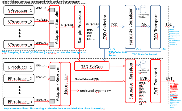
Ideal Event / Telemetry System, within the context of single Node instance
The focus for this epic will be on the event pipeline with telemetry work mainly focused on TSD transport using a common bus and object model. It is a goal that the same transport bus be used for both events and telemetry if possible.
Telemetry Collection
The OPNFV Barometer project is focused on telemetry and event collection and transport in a cloud environment. Most of the work to date has focused on defining what should be collected and adding improvements to collectd which Barometer has chosen as the telemetry collection agent. The Barometer group is currently defining changes for collectd to allow for sample rates to be higher than transport rates as well as the addition of additional thresholding capabilities. In addition, collectd has been been enhanced such that is possible to write both polled plugins and event-based plugins. Part of the prototyping phase of the Service Assurance epic will be to evaluate if collectd can be used as the basis for the real-time fault management agent described in the following section.
RT Fault Mgmt Agent (RFE x)
As mentioned above a significant portion of this epic will involve the prototyping of a "local" fault management agent that meets requirements outlined in the Telco Requirements section.
Background
Currently available cloud monitoring projects do not adequately address the performance requirements of NFV. Specifically, the traditional enterprise monitoring systems that have been adapted to the cloud were not built to detect fault conditions within a second of their occurrence, much less within 10s of milliseconds.
Monitoring systems available in OpenStack originated in the enterprise data center. While their telemetry capabilities provide adequate monitoring of resource usage, enterprise availability monitoring systems typically provided up time status with detection time resolution measured in minutes. In contrast, telco environments typically require the time for detection + notification + remediation to be less than 50ms. While NFV is an evolution of the classic telco environment, emphasis is still placed on reliability and availability. There may be some relaxation of the 50ms requirement, service provides still require reaction times under a second.
Collectd is one such legacy monitoring framework that has been adapted for the cloud.
The idea is to complement CollectD with a real-time Fault Mgmt Agent. The Agent will have the following characteristic:
- Event driven monitoring. Polling-based monitoring software can be optimized such that it can run with < 10ms sample times. However, such low sample rates can take a toll on CPU usage. Events that must be detected quickly should be monitored by Move from Polling to Event driven detection.
- Monitor a set of KPI and react locally when possible (following particular rules)
- Monitor a set of KPI and fwd an event to a RT Fault Mgmt Bus so that MANO System(s) can react (in context of NFV, VIM/SDNC, VNFM or NFVO in the order of increasing scope)
- The fault management agent (whether Collectd or something different) should be configurable during runtime through a common communication mechanism. Ideally, the data model for telemetry and event definition will include the necessary control structures to be able to configure the RT Fault Mgmt Agent.
As mentioned previously, part of the work will be determining if collectd is the correct local for the local agent.
RT Fault Mgmt Bus (RFE x)
Messaging solution needs (from FM events delivery perspective, TSD is slightly different - more throughput than latency focused):
- Low latency event delivery (microseconds p-tpt, sub 1 ms target for up to 64 recipients in absence of delivery errors)
- Fault tolerance on messaging
- Reliable event delivery
- Maintain low latency characteristics even in presence of faults (translates to fast delivery error detection and fast retransmits)
- Should support multiple delivery semantics (one-to-one, one-to-many)
- In the case of one-to-many, should be able to support ordering of the delivery on the "copy" point to prioritize the delivery for latency optimization (alternatively some kind of broadcast and select with reliability related additions to ensure delivery for all subscribers could be potentially interesting model)
- Either connectionless, or persistent connections if connection oriented - connectionless would need to add reliability mechanisms
- Messaging solution needs to support awareness of the underlying network redundancy (esp. If messaging is "overlay" solution); many fault messages are expected to be network connectivity related, therefore this is esp. Important when the same network is potentially used for fault indication messaging delivery
- Standardized event format with flexible encodings (ideally both binary "TLV" and various ASCII encoded schemes over the same underlying messaging solution)
- Supports concepts such as channels, domains / namespaces to integrate with the receiving sub-systems and to reduce the message routing/parsing overheads to deliver the messages)
- Ideally same messaging solution for both telemetry data and events (all F_APS messages) … bonus would be to support the configuration transactions with the same messaging - but that is not a requirement
- Should be already supported by the telemetry and event persistency solutions and/or other associated common infrastructure subsystems
- Should support tracing, including latency metrics
- Should support message prioritization across the stack